Features:
- Adjustable turn-on temperature from 150 - 240 degrees
- Turn-off temperature 10 degrees less than turn-on
- 3/8" NPT water jacket thread-in sending unit
- 30/40 Amp heavy-duty relay included in kit, necessary if electric fan draws over 10 Amps
- A/C override circuit included
- Designed for dual fans
- Maximum capacity: 25 Amps
Specs- Thermal Switch Style: Adjustable fan control kit
- Sending Unit Style: Thread-in
- Sending Unit Included: Yes
- Sending Unit Thread Size: 3/8-18 NPT
- Fan Quantity: Single/Dual
- Adjustment Range: 150-240 degrees F
- Relay Included: Yes
- Wiring Harness Included: Yes
- Manual Override Switch Included: No
- Air Conditioning Relay Included: No
Parts
Installation Instructions
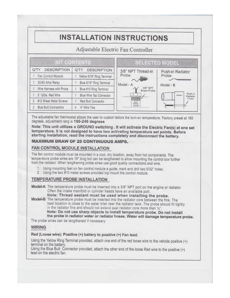
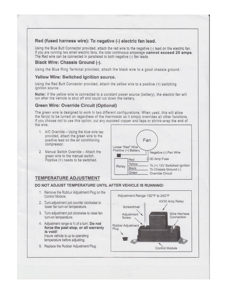
How To Diagnose DER-16749
First off, you must have access to a DIGITAL VOLT AND OHM METER (DVOM). You cannot use a test light on the diagnosis of this unit. As with any automotive electrical install, make sure your vehicle’s battery is in proper operating condition (12.5V or higher). If your battery is weak this can cause functionality issues with the controller unit.
If your fan is not cutting on after install you will need to go over each connection. Check continuity on each connection made. This will involve you using the resistance or ohm setting on the DVOM before and after each connection. If you show an open or OL reading, then you need to fix this connection.
BLUE WIRES FROM FAN- These will go together and will be tied into the 12V battery voltage. Using the DVOM, verify you show 12.5V or more at the batt when setting this up. Check continuity on each connection made before and after each connection.
BLACK WIRES FROM FAN- These will go together and will be tied into the red wire off of the controller. Check continuity on each connection made before and after each connection.
TEMP PROBE- The most accurate signal for this will be on the thermostat housing. Putting this in any other location can cause issues with the fan cutting on. If your kit did not include part number LRS-8592A then you will need to incorporate this into your installation. LMR recommends to always use this on a vehicle equipped with a thermostat. If your car is running an open thermostat, the coolant may never reach the correct temp depending on conditions.
YELLOW WIRE FROM CONTROLLER- This needs to be hooked up to a valid 12V switched ignition circuit. Using your DVOM, you can go to your fuse panel and find a 12V circuit that is only hot when the key is on. Do not hook this up to any circuits that have a full time key off 12V source.
BLACK WIRE FROM CONTROLLER- This wire needs to be your ground connection. As with any ground, please make sure the surface if free of any paint or contamination. You can also use your DVOM to verify your ground. Hook the red jumper from the DVOM to the positive side of the battery. Then put your black lead on the ground wire connection you have made. You should read battery voltage at this point. Even if you are using an existing ground on the car, it may not be a good one. Always use the DVOM to ensure the ground is adequate.
GREEN WIRE FROM CONTROLLER- This wire is designed to work in 2 different configurations. When this wire is used, this will override the temp probe completely. If you choose not to use this, then make sure it is completely sealed off where it cannot make any connections to a power or a ground.
If you do choose to use the override circuit for your A/C, then tap this wire into the positive lead off of the compressor. Using your DVOM, check this connector for battery voltage. Check continuity on each connection made before and after each connection if fans do not kick on when the A/C is actuated.
If you do choose to use the override circuit for manual switch, attach the green wire to the positive side of the switch. Check continuity on each connection made before and after each connection if fans do not kick on when the switch is actuated.
FINAL ADJUSTMENTS OF THE TEMP SETTING- When setting the temp range for the fans, you MUST HAVE THE CAR TO OPERATING TEMP! If the engine coolant is cold and not up to temp, then the fan controller will not work. Also, make sure you have checked proper levels of your coolant and that your thermostat is opening when intended. If you have access to a laser style thermometer, point this as close to the temp probe as you can on the housing. Try to get the fans cutting on as close to the thermostat opening point as you can.
FANS SPECIFICATION- This unit will be rated at a maximum capacity of 25 continuous amps. Please make sure to read over your fans specifications and read your amperage rating. If it shows anything higher than the recommended 25 amp rating, then this controller will not work.