



1979-93 Mustang Parts
Help simplify your rear disc brake conversion with this Ford E-brake adjuster lockout from LMR!
When converting to rear disc brakes, it's common practice to have to majorly modify your factory hand brake to lock out the self-adjusting mechanism that the drum brakes require. Rather, bolt on this simple bracket with a single bolt to defeat the mechanism. Built from a durable steel construction and made to be installed around the e-brake handle mechanism, this bracket will not fail. With only a small tab to trim and a single hole to tap, the installation couldn't be simpler. You can't go wrong using a Ford Original part on your Fox Body to ensure the best fit and quality in the market.
INSTALLATION INSTRUCTIONS
1. Disconnect the battery ground cable.
2. Remove the console
3. Disconnect and remove the parking brake indicator lamp switch.
4. Remove the parking brake control assembly retaining bolts.
5. Release cable tension by pulling the control assembly forward far enough to rotate the self adjuster reel while an assistant inserts a suitable steel lockpin through the hole in the lever and behind the cam on the sector gear. This locks the sector gear in the “cable released” position.
6. Disconnect the cable barrel from the self-adjuster reel and remove the control assembly from the vehicle.
7. Position the control assembly in a vise.
CAUTION The plastic handle cover must be removed or it will be damaged during the cutting procedure. Covers are not serviced separately.
8. Remove the plastic handle cover by disengaging the locking tabs (one on each side) from the underside of the handle using a small screwdriver or other suitable tool.
CAUTION Be sure to cut only the kickout tab. Do not cut the handle or any other part of the control assembly
9. Using a suitable cutoff tool, remove 11-13 mm from the end of the kickout tab on the self-adjust paw. Remove any burrs.
10. Thoroughly clean all metal shavings and grinding debris from the control assembly.
11. Apply Motorcraft XL5A MultiPurpose Grease Spray (or equivalent) to the control assembly self-adjuster pawl and sector.
12. Reinstall the handle cover.
13. Remove the control assembly from the vise.
14. Insert the parking brake cable barrel into the hole in the self-adjuster reel, then route the cable around the reel.
15. Position the control assembly in the car by sliding the rear mounting tab under the console support bracket then line up the front mounting tab with the bolt hole.
16. Install the bolts. While holding the control assembly as far rearward as possible, tighten the bolts to 18 Nm (13 lb-ft).
WARNING KEEP YOUR FINGERS AWAY FROM THE PARKING BRAKE CONTROL ASSEMBLY TO PREVENT INJURY.
CAUTION Do not remove the lockpin without first making sure the parking brake cable is properly connected to the control assembly. Pin removal releases the tension in the ratchet wheel causing the spring to unwind and release tension. If the pin is removed without the cable properly connected, the entire assembly must be removed to reset the cable tension.
17. Remove the lockpin.
18. Apply and release the parking brake control four (4) times, ending with the lever pulled up to its maximum apply position. Make sure the self-adjust pawl tooth fully engages the sector gear (the pawl tooth must not be “perched” between two teeth of the gear).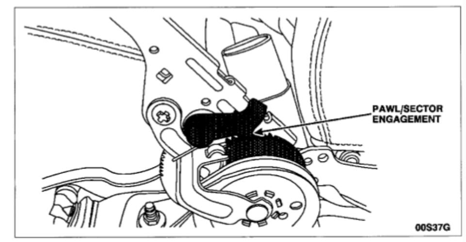
CAUTION The torque specification on the self-tapping screw is very low. Do not use power tools to tighten this screw. Do not overtighten the self-tapping screw or the threads in the hole will strip. If this occurs, the entire control assembly must be replaced.
19. Position the over-bracket on the control assembly as shown in the illustration. Make sure the over-bracket mounting hole is aligned with the lockpin hole on the control assembly. Install the self-tapping screw and tighten to 3.0 Nm (27 in-lb).
20. Install and connect the parking brake indicator lamp switch.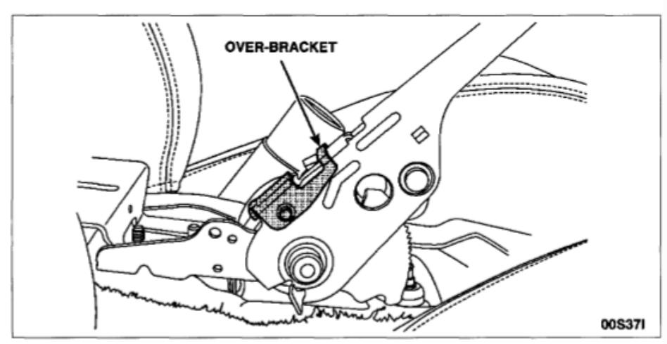
21. Install the console.
22. Connect the battery ground cable.
23. Apply and release the parking brake control several times. Make sure the parking brakes apply and release, the BRAKE indicator lamp on the instrument panel comes on when the parking brakes are applied when the key is on, and the lamp goes off when the parking brakes are released.