
SHOP

1994-04 Mustang Parts
Free Shipping on qualifying orders over $99* Details
LMR showroom & will call pickup service will be closed beginning Monday 9/21/26 for renovations until further notice. Need help? Contact Us.

1999-2004 Mustang Odometer Fix

Created by Brian Horn / 5 min read
Date Created: 4/24/2026
Last Updated: 4/28/2026

Follow along with this handy guide to fix the odometer in your New Edge Mustang

Viewing this install and using the information shared is subject to the terms set forth here - View the LMR Install Instructions Disclaimer.

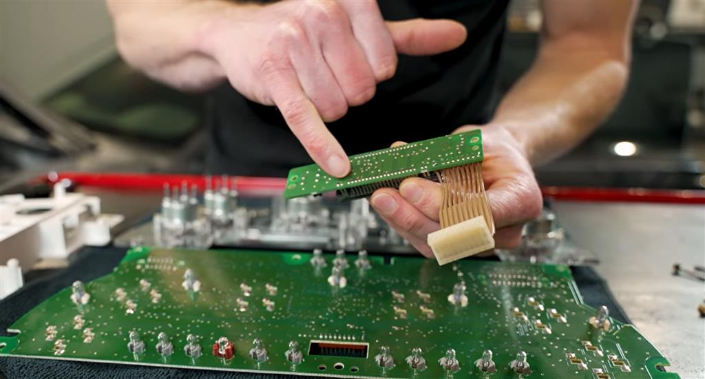
Is the odometer not working in your New Edge Mustang? You're not alone. A common problem on just about any 1999-2004 Mustang is that the digital odometer readout will become intermittent or completely go away. While there could be other underlying issues, the main issue is usually a damaged solder on the back of the printed circuit board. In this video, Landan shows the process of diagnosing the issue and how to fix it.


Product Links 1994-2004 Mustang Dash Parts


Tools & Supplies Needed

Basic Tools

  • 7mm socket or nut driver
  • Phillips screwdriver
  • T15 Torx driver
  • Trim removal tool
  • Ratchet
  • Flashlight

Electronics Repair Tools

  • Soldering iron (fine tip preferred)
  • Rosin-core solder
  • Magnifying glass OR smartphone macro camera
  • Isopropyl alcohol
  • Cotton swabs
  • Small brush

Optional


  • Replacement cluster lens if scratched
  • Anti-static gloves
  • Multimeter 

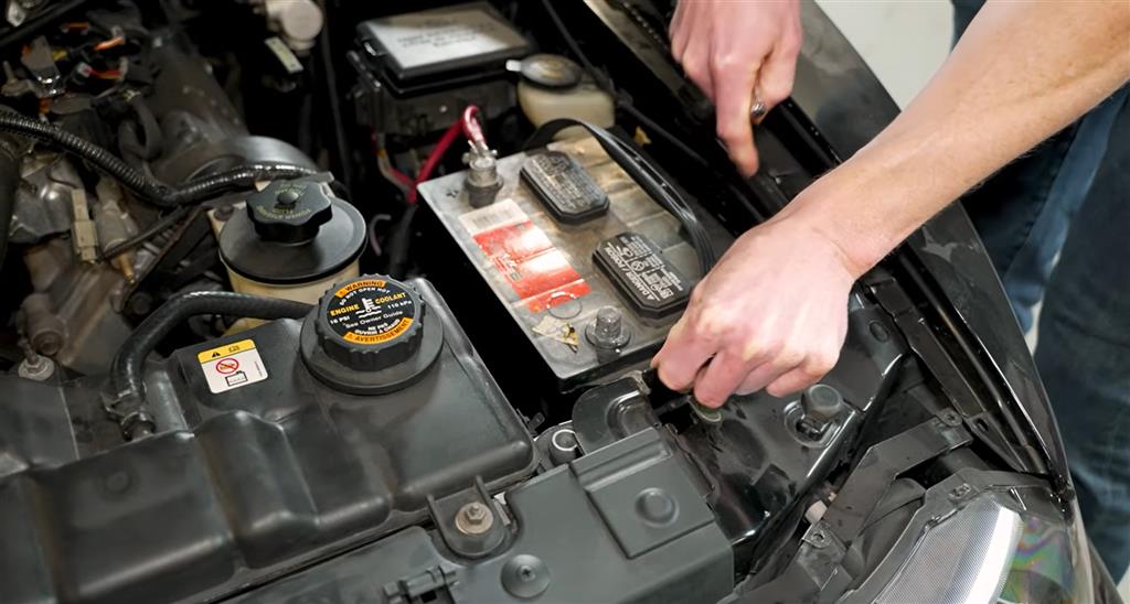
Step 1: Disconnect the Battery

Before touching the cluster:

  1. Open hood.
  2. Disconnect the negative battery cable.
  3. Wait 5–10 minutes.

This prevents:

  • Short circuits
  • Airbag issues
  • Electrical damage


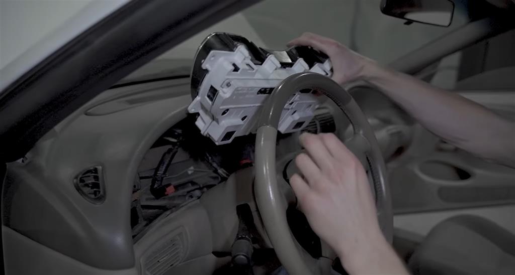
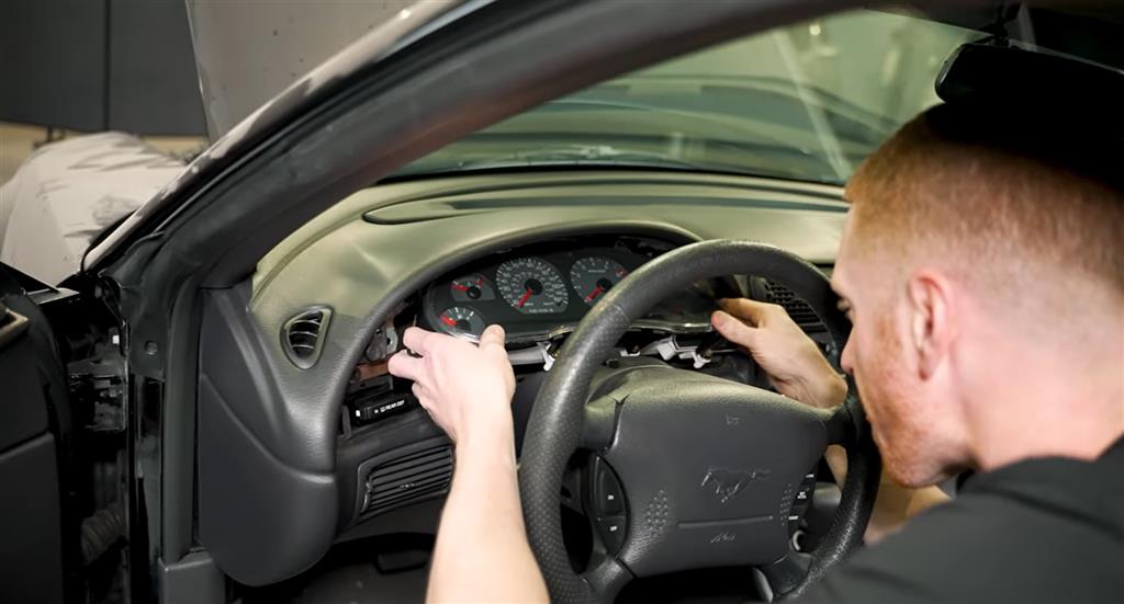
Step 2: Remove the Instrument Cluster

Remove Dash Bezel

  1. Lower steering wheel fully.
  2. Remove trim bezel around gauges/radio.
  3. Remove screws securing bezel.
  4. Carefully pull bezel outward.

Remove Cluster Screws

  1. Locate cluster mounting screws.
  2. Remove them.

Pull Cluster Forward

  1. Tilt cluster out slowly.
  2. Reach behind it.
  3. Disconnect electrical connectors.

If a clip is stuck:

  • Use trim tools
  • Needle nose pliers
  • If broken, replacements are inexpensive


Step 3: Move Cluster to Workbench

Take the cluster somewhere clean and well lit.

Use:

  • Soft towel
  • Table surface
  • Good overhead lighting

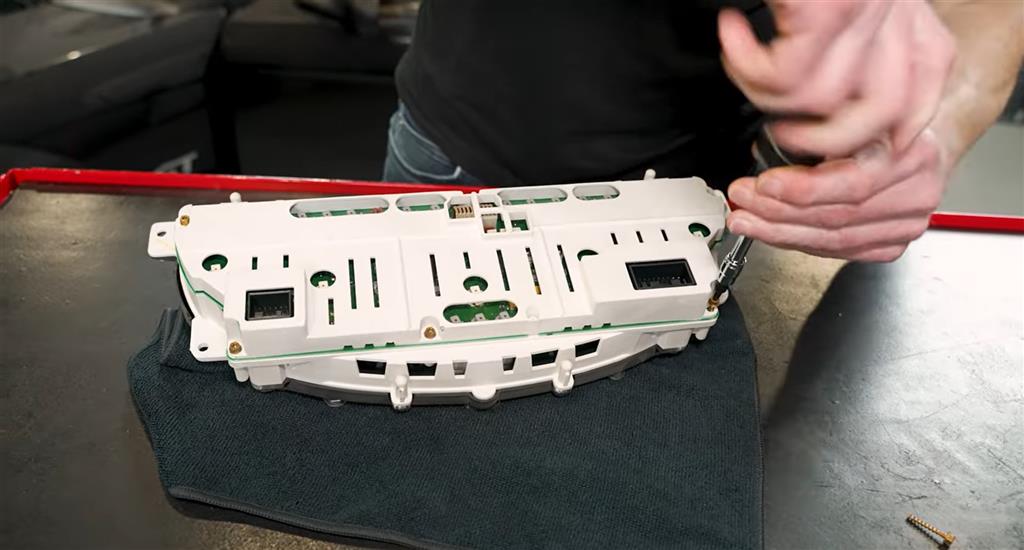
Step 4: Remove Rear Cover

Using a T15 Torx driver:

  1. Remove screws holding rear housing.
  2. Lift backing plate off.

Now you’ll expose:

  • Circuit board
  • Gauge assembly
  • Odometer module


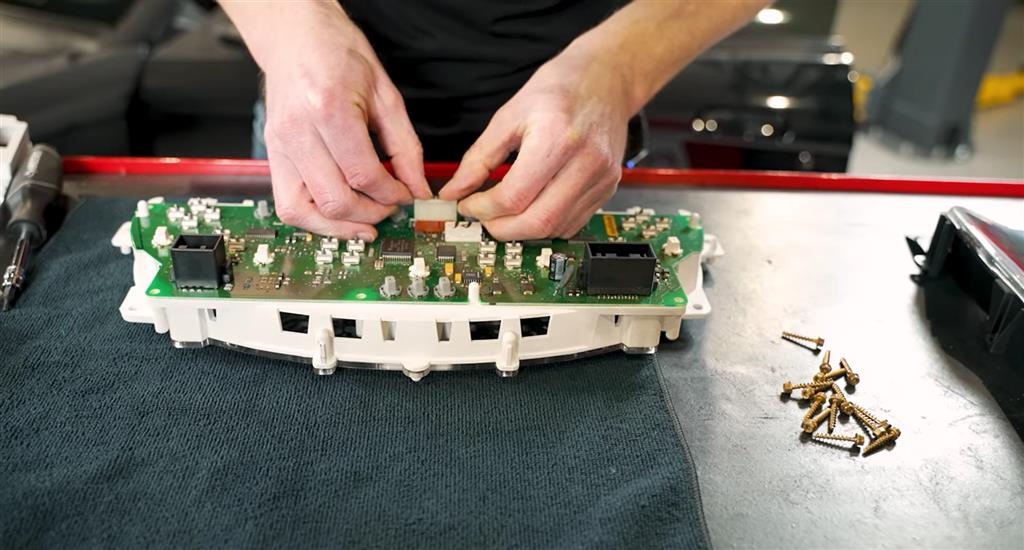
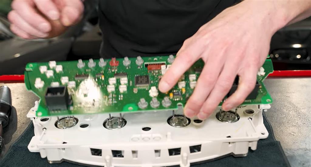
Step 5: Separate Circuit Board Carefully

Be gentle here.

  1. Slowly work the circuit board away from housing.
  2. Watch for ribbon cables.
  3. Disconnect any plug-in connectors gently.

Do not force anything.

Avoid removing needles unless absolutely necessary.

Step 6: Inspect for Dust / Damage

Now is a great time to clean:

  • Dust inside lens
  • Gauge face debris
  • Old dirt buildup

Use:

  • Microfiber cloth
  • Compressed air lightly
  • Soft brush

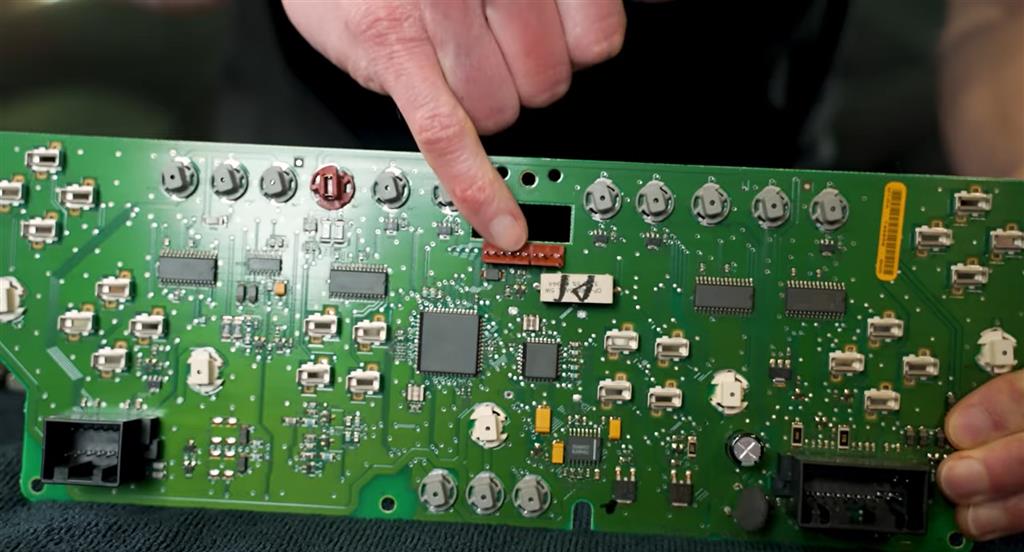
Step 7: Inspect All Solder Joints Closely

This is the critical step.

Use:

  • Smartphone macro zoom camera
  • Magnifying glass
  • Bright flashlight

Check solder joints around:

Main Connector Pins

Where harness plugs into cluster.

Odometer Display Board Pins

Small board holding odometer screen.

Ribbon Cable Connections

Look for cracks or lifted solder.

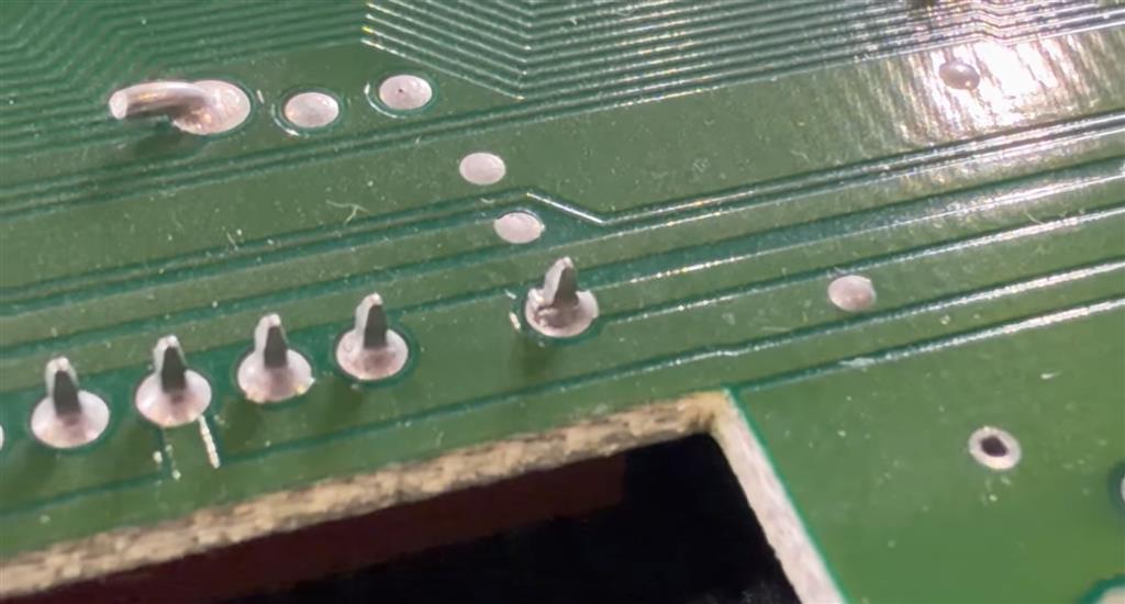
What a Bad Solder Joint Looks Like

Look for:

  • Circular crack around pin
  • Dull gray solder
  • Ring separation
  • Movement when lightly touched
  • Tiny gap at base of pin

Often only one pin is bad.

That single pin can kill the odometer.

Step 8: Repair the Bad Joint

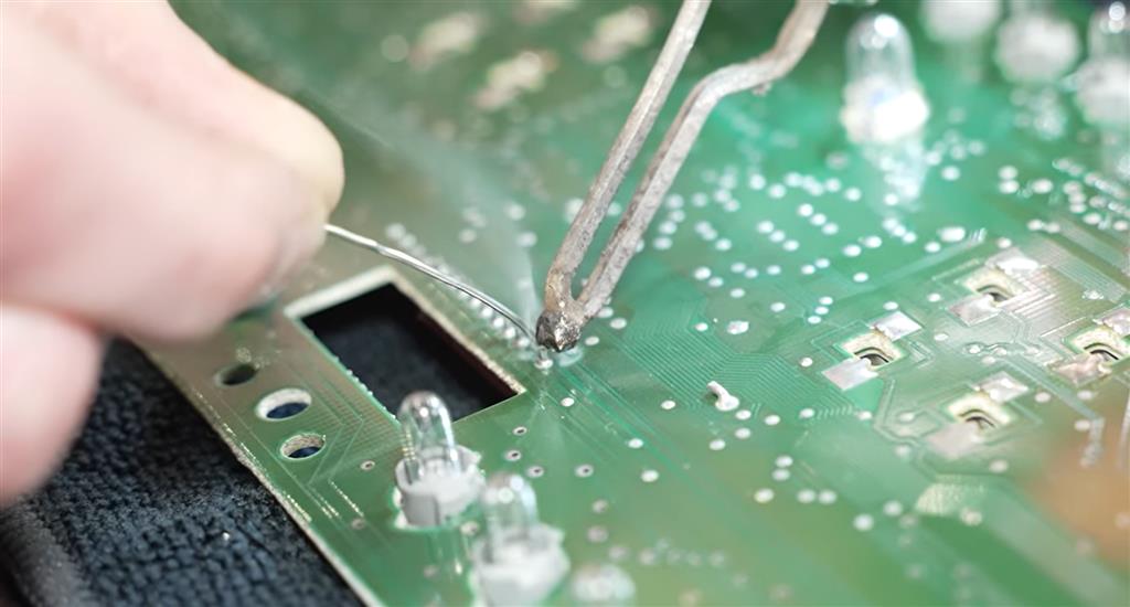
How to Resolder

  1. Heat soldering iron.
  2. Touch tip to old solder joint.
  3. Add tiny amount of fresh solder.
  4. Let solder flow smoothly around pin.
  5. Remove iron.
  6. Let cool naturally.

Goal:

Smooth shiny cone-shaped solder joint.

Important

Do NOT:
  • Use too much solder
  • Bridge adjacent pins
  • Overheat board


Step 9: Inspect Other Joints While You're There

Even if only one looks bad:

Reflow any questionable joints now.

Especially:

  • Connector pins
  • Odometer module pins
  • High stress mounting points

Prevention now saves future work.


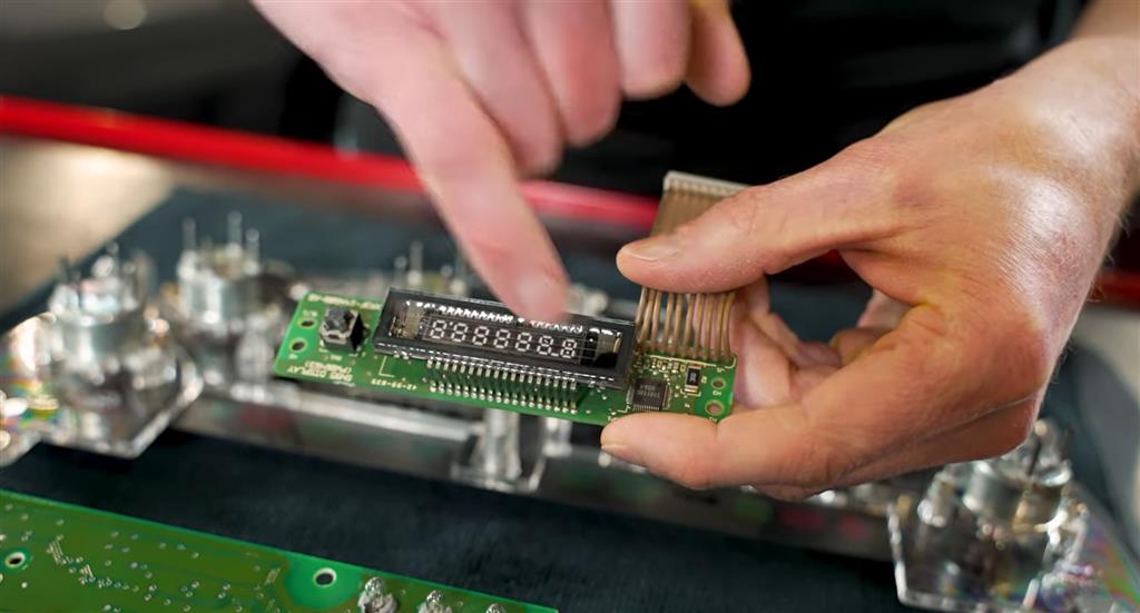
Step 10: Check Display for Burn Spots

While the cluster is open, inspect the odometer LCD.

Look for:

  • Dead pixels
  • Burn marks
  • Dark spots
  • Missing segments

If the solder repair works but the display remains damaged, the LCD may need replacement.

Step 11: Reassemble Cluster

Reverse disassembly:

  1. Reinstall the white housing.
  2. Reconnect ribbon cables.
  3. Seat circuit board fully.
  4. Install the rear cover.
  5. Tighten T15 screws evenly.

Do not overtighten.


Step 12: Reinstall Cluster in Car

  1. Reconnect electrical connectors.
  2. Slide cluster into dash.
  3. Install mounting screws.
  4. Reinstall trim bezel.
  5. Reconnect the battery negative cable.


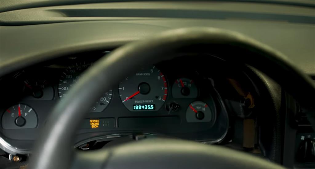
Step 13: Test Operation

Turn the ignition key to ON.

Check:

  • Odometer lights up
  • Digits stable
  • No flickering
  • Gauges function
  • Backlighting works


Step 14: Road Test / Long-Term Verification

Sometimes the problem is temperature-related.

Monitor for several days:

  • Cold starts
  • Hot afternoons
  • Rough roads
  • Night driving

If it remains stable, the repair was successful.

If It Still Fails

If the odometer still cuts out after the solder repair:

Possible Causes

1. Damaged Odometer LCD Board

Requires replacement.

2. Ribbon Cable Failure

Intermittent internal break.

3. Cluster Power / Ground Issue

Check harness and grounds.

4. Headlight Switch / Illumination Circuit

If cluster lighting also fails.

5. Full Cluster Internal Failure

May need rebuilt cluster.


About the Video

1999-2004 New Edge Mustang Odometer Fix | Here's What to Do

Check out our YouTube channel for even more tech tips, installation videos, how-tos, and more. The best place to go for anything Mustang related!

Published on 2026-01-19
A common problem on just about any 1999-2004 Mustang is that the digital odometer readout will become intermittent or completely go away. While there could be other underlying issues, the main issue is usually a damaged solder on the back of the printed circuit board. In this video, Landan shows the process of repairing a damaged solder joint.
Thumbnail image of the author of this article, Brian Horn.

About the Author

Brian has been with LMR in a variety of positions since 2017. While working mostly in the warehouse and shipping your orders, Brian is now taking on a new role of writing articles for us. Read more...